
Contents
Table of Contents
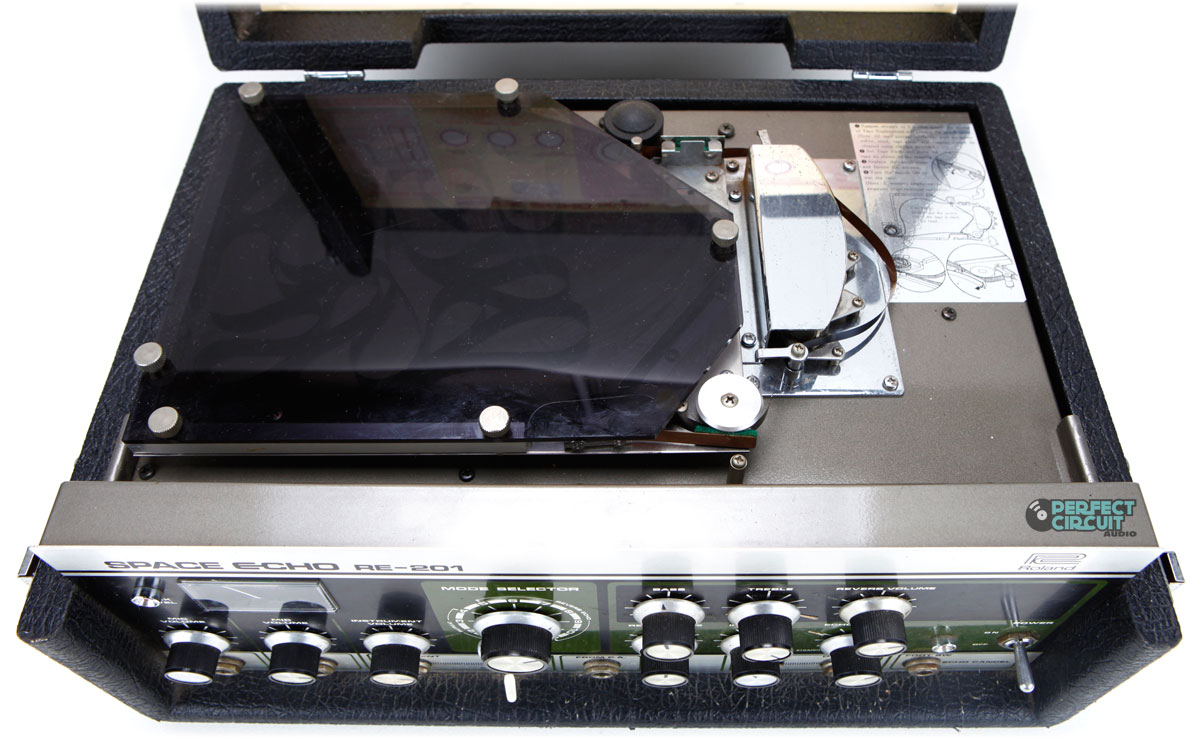
Recently I bought a RE-201 which optically was in quite mint condition. Nevertheless most of the potis are kind of noisy when turned. Even worse, the mode selector, a rotary switch, had a serious issue: in mode 1 and 6 no effect could be heared at all.
I was asking Shane from www.echofix.com and he kindly replied he thinks the problem could be dirt in the rotary switch. He suggested to spray some cleaner in it. I did so but unfortunately it didn’t solve the problem.
So I started to think about disassembling the rotary switch. I was told not to do so since it normally doesn’t end in a good result. Same advice I read in some posting on a web forum. .
But what other option did I have? It’s not working properly, it either needs to be fixed or replaced. I quickly checked if there are options to replace the switch (there are, Shane has some in store and I also found some other sources for similar – not the same – switches), so I decided to give it a try.
Long story short: It worked. But it was quite a bit of work and it takes a lot of patience and fine-motor skills.
For those out there running into a similar situation, below you can find a description of how to service the rotary switch.
Please note
Although the rotary switch can be successfully de- and reassembled, it requires some skills to do so. I therefore advice to only do this as a last option and only if you feel confident you have the skills needed.
In case you feel unconfident, don’t do it. There are a bunch of repairers all over the world you can ask to do the job for you. Shane from www.echofix.com is one of those.
Preparation
If you’re not repairing or maintaining similar devices on a daily base, be prepared you might have to invest some hours to get the whole work done. Basically it’s not too much work per se, but you will have to do your own learning curve and it’s very likely it won’t work on the first shot.
First get yourself a place where you have space. Be aware there as some smaller parts in the rotary switch and you may not lose one of those, since you won’t get the switch working again without.
Tools
Tools i used:
- Bunch of screw drivers, mainly smaller ones (crosstip for encloser)
- Wrench
- Electric soldering iron incl. a desoldering pump and solder of course
- clean (!) cleaning rags or similar
- soldering aid
- DeoxIT® Fader cleaner
- Pincette (very useful for fine motoric work)
Open the case
To open the case you have to:
- remove 5 screws from the bottom
- remove 1 screw on the left and the right side each
- remove the brackets on the top left and top right side.
Once this is done, carefully lift the space echo from its case. Turn the gear to one side and make sure you do not damage the cables to the echo tank.

Then remove the cables from the echo tank and mark one to remember which one was plugged into which side of the tank.
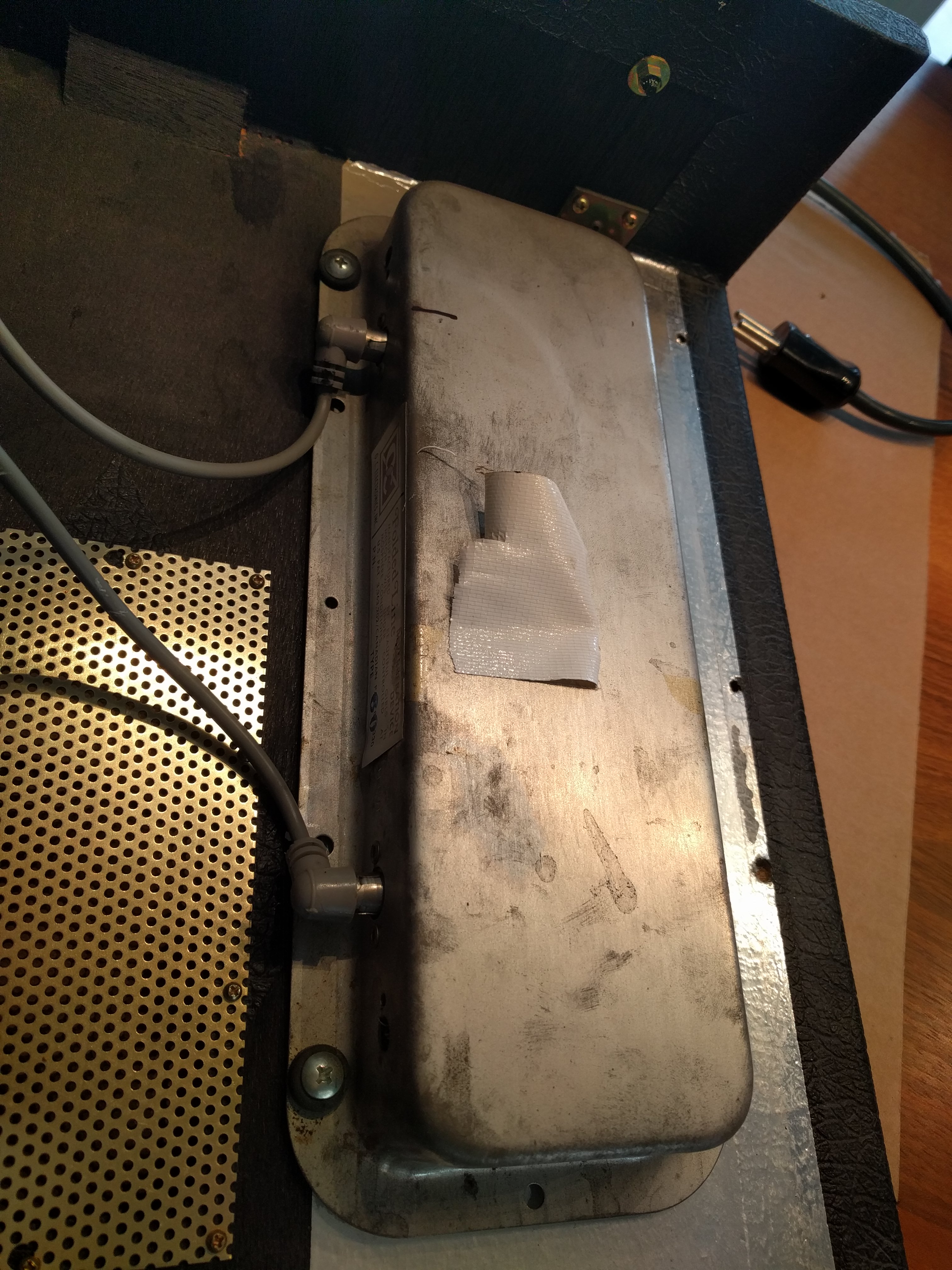
Once the tank is unplugged, you can remove the case and turn the gear upside down.
Dismantel
First the knob needs to get removed. You can do so by losening the related screw. Next step is to remove the wrench and washer.


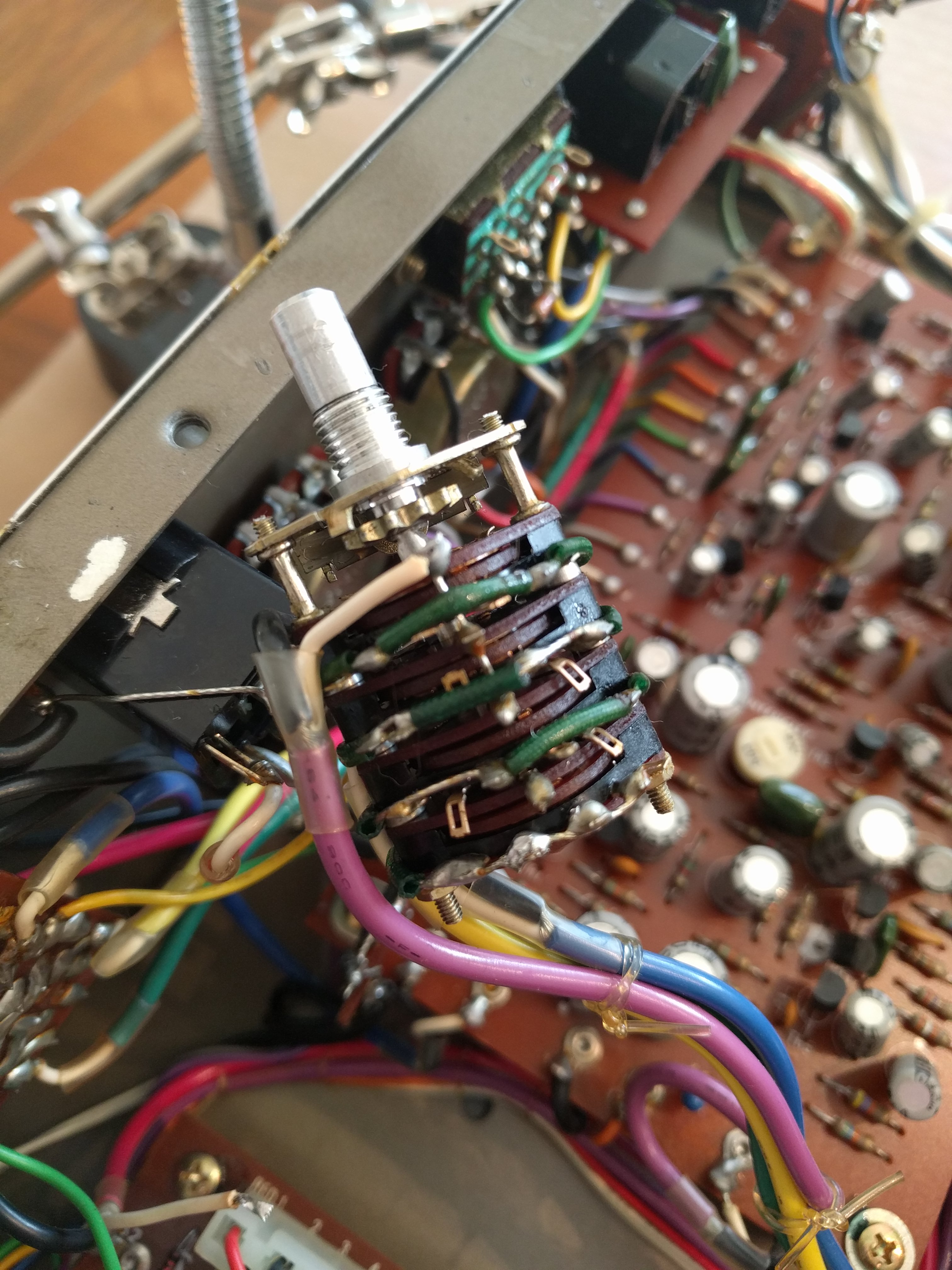
Before you can draw out the switch, you need to remove the component marked with (1) on the photo below. You can do so be removing its screw and push it a bit to one side. Also you need to remove the connector marked with (2) below.
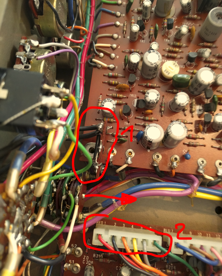
Now you can pull the switch out of the hole. Attention: Just move it a bit, since it’s still soldered and the light green and white cable in the lower left corner of the picture above are quite short; if you move too much, you will tear the cable off the switch.
Desoldering
Before you start desoldering and disassembling: Take a picture from every angle. Make sure you can see where each cable comes from and ends. Please note that some of the cables could be soldered a way they are overlapping others.
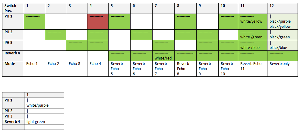
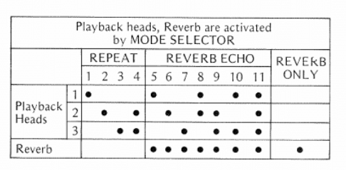
The table below shows which cable is soldered to which soldering point. “——-” is indicating a soldering point of the green bridge cables, “|” same for the bridges between different potis. Where a cell contains a color, the related cable is soldered at this position.
PH stands for “play head” where PH1 is the poti on top, Reveb 4 the poti at the bottom. The horizontal numbers indicate the switch position (each poti has 12 switch position – of course equal to the number of play modes).
The second, smaller table refers to the electrical ground. The soldering points for head 1 to 3 are shorted (indicated by “|”).
Soldering points and cables
When desoldering I used a desoldering pump to remove some of the solder to make sure it’s not dripping to a platine.
Please note: Do not desolder the dark green cables wrapped around a poti. They are used to connect/bridge some of the 12 positions of the connector and do not need to be removed.
Do not desolder green bridge cables
Disassembling
The rotary switch basically is a stack for 4 individual potis in a row. The upper 3 potis are controlling the playback heads 1, 2 and 3 (echo) while the lowest poti is controlling the reverb (tank).
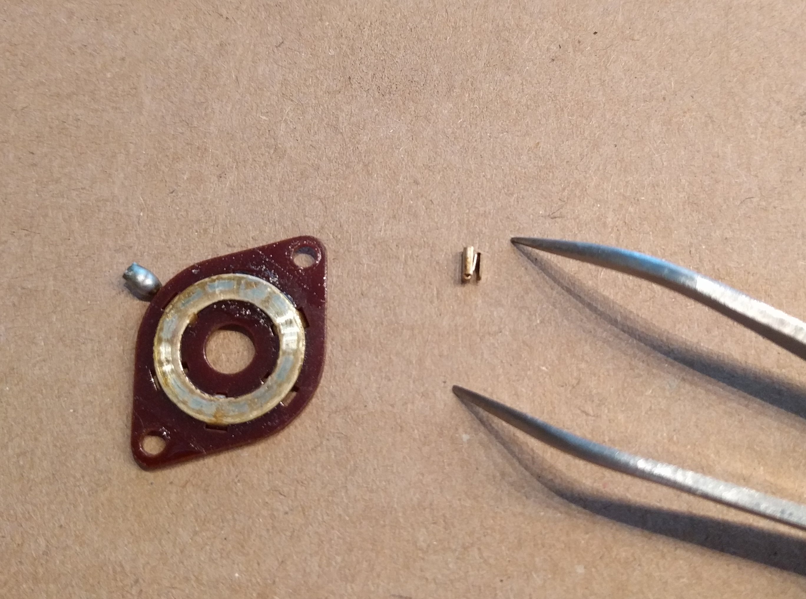
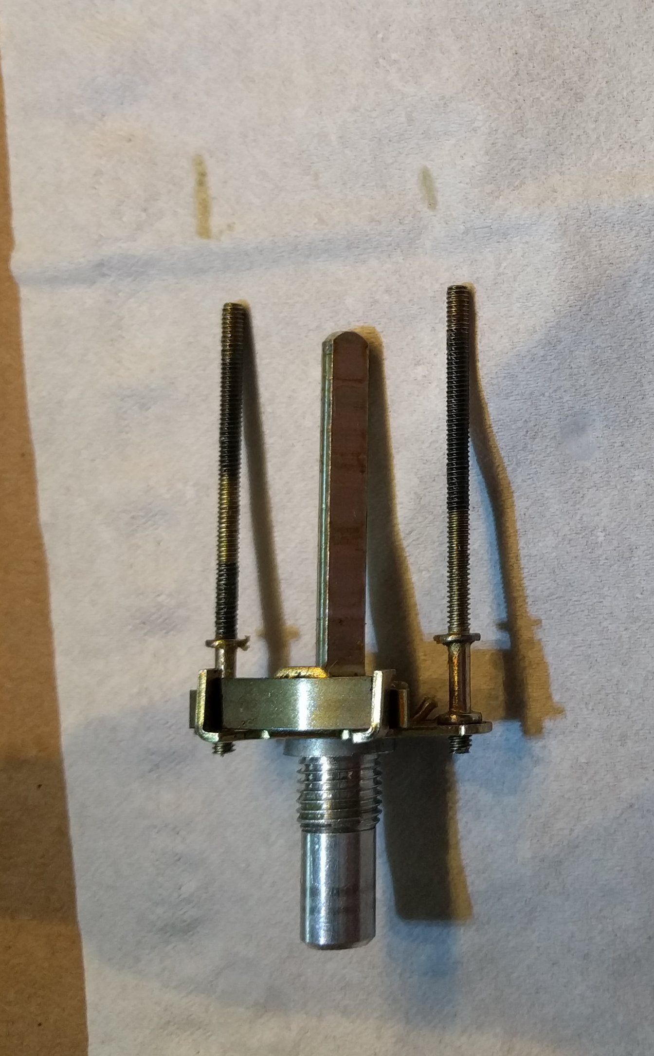
To disassemble you have to remove the two nuts on the threads. After this carefully start to remove layer by layer. Please be aware each poti contains a small loose part (contact). Don’t lose, you won’t get the switch working again without. In between the potis you will find two distance holders, one on each side. Also take care not to lose one of those.
Cleaning
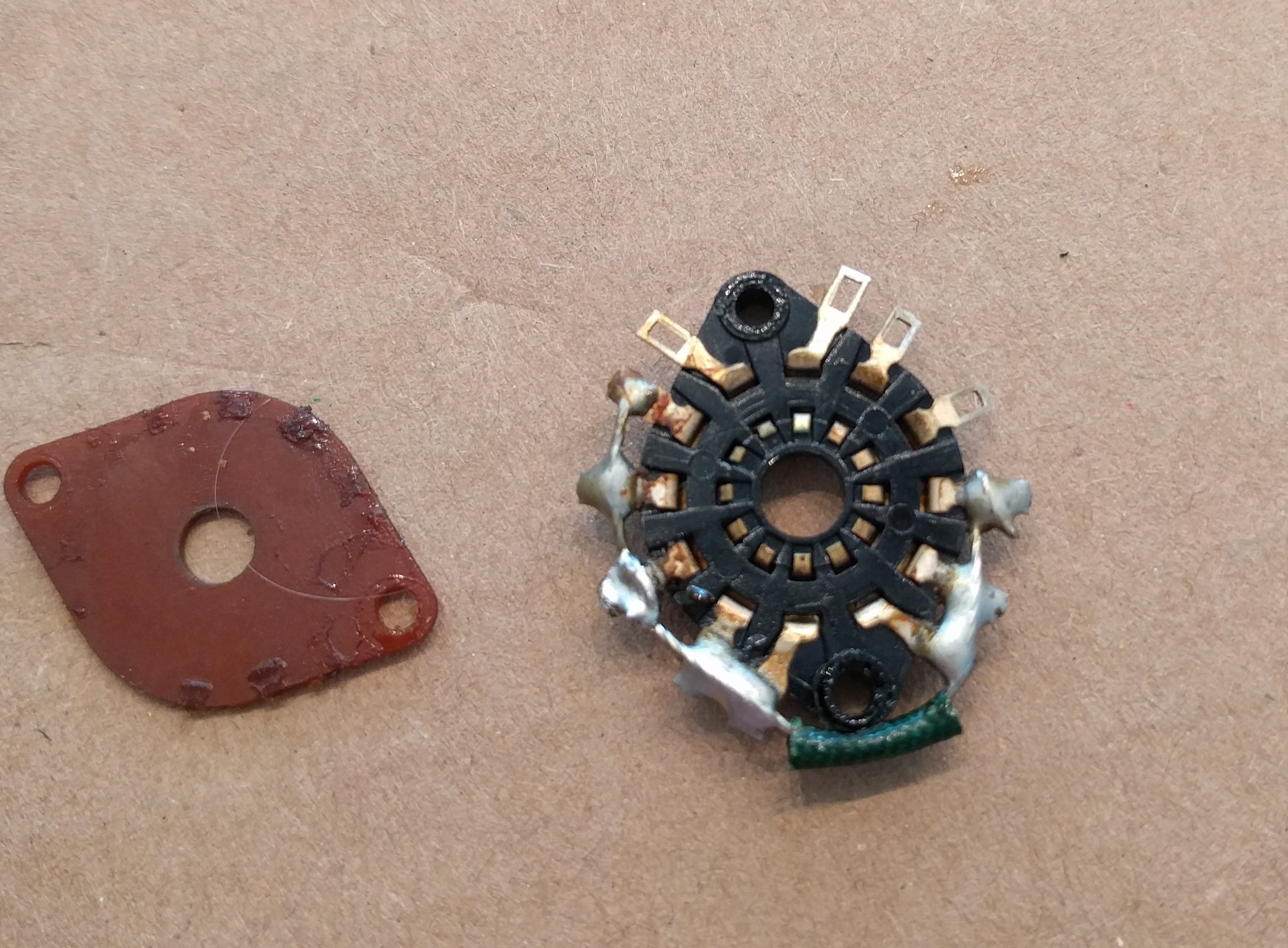
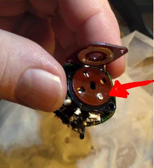
As you can see in the picture above, the slice is pretty dirty (and this wan’t the worst one). Same as well for the plastic parts in the poti.
I cleaned all parts with cotton sticks and DeoxIT® Fader cleaner. Please note: Do not use pure alcohol or similar since it will harm the materials.
And don’t forget the brackets:
Not to mention: Do a full clean up of everything inside the case, as good as possible. All dirt removed is dirt that may not find its way into your potis.
Reassembling
After cleaning all parts, it might look similar on your table as what you can see below (please note, there are more parts than shown on the picure):
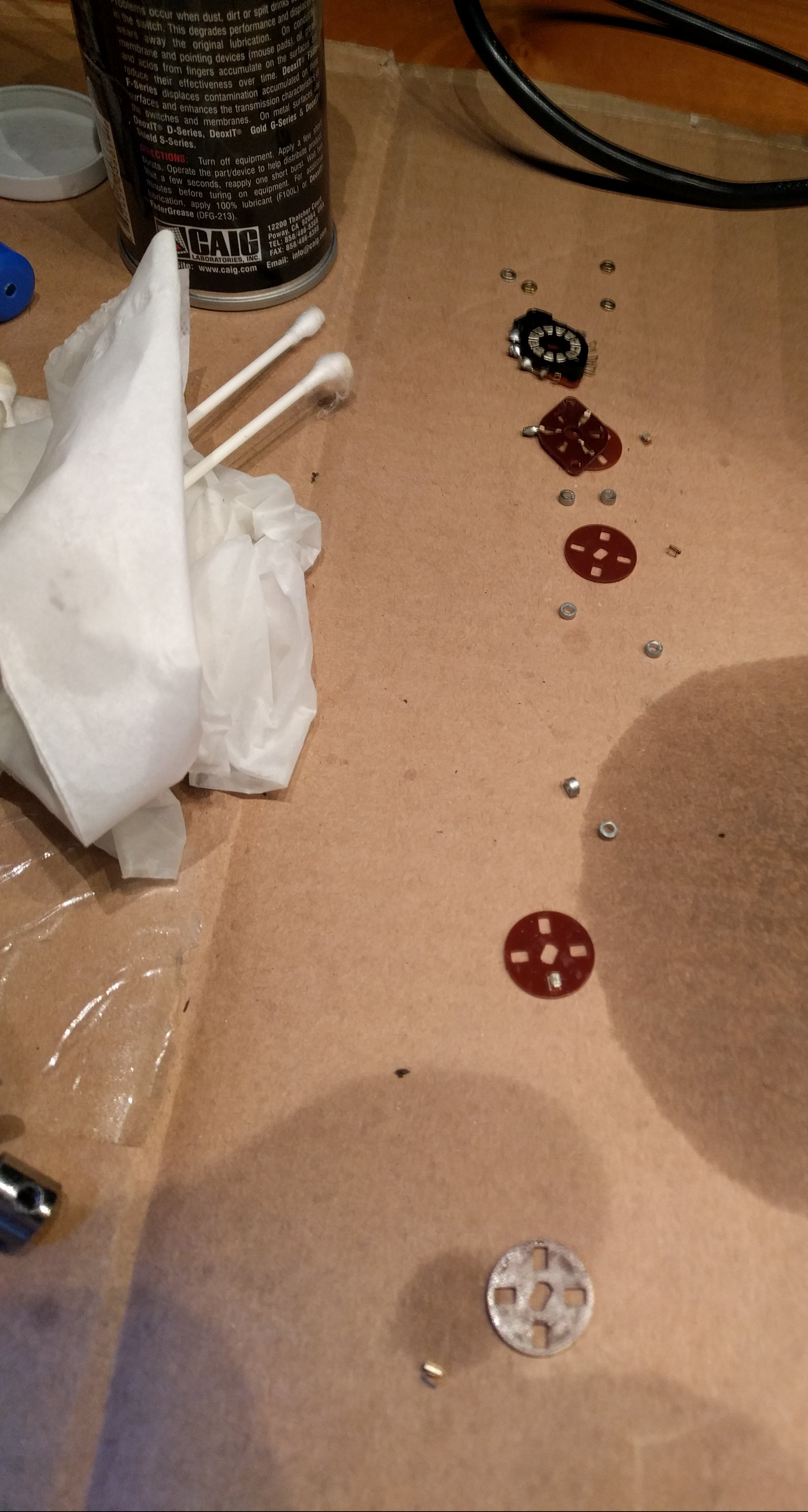
Start re-assembling in the correct order and orientation (!). Make sure you place the plastic slice with the five holes (see picture above) with the right side up. On first sight orientiation seems to be unimportant, but that’s wrong. If you look closely you will see that orientation matters because when mounted the angle of the holes are slightly different. Make sure to choose the right orientation (the hole needs to fully cover the contact pin of the underlying element) and the same orientation for all of those slices. Then place the little contact element into one of the spaces. Please note: It does not matter which of the four spaces in the plastic slide you chose, but you need to chose the same for all four slides!
Take care the contact element does not drop out during the further assembly steps.
Each slice got a short spray of cleaner before putting the next element on top ot it.
Once the last slide has been mounted, tighten the nut. Do not tighten too much and make sure the pressure on both nuts is similar, otherwise the switch may not be turned and you might even damage the contacts. On the other side it needs to be tighend enough so the contact and slides do not have too much space in between, since the contacts need to stay in place and permanantly make good electrical contact.
Soldering
Soldering should be easy, you only have to make sure to connect the right cables with the right soldering points. That’s where your photos and the table above are useful. Also make sure to not accidentially create solder straps.
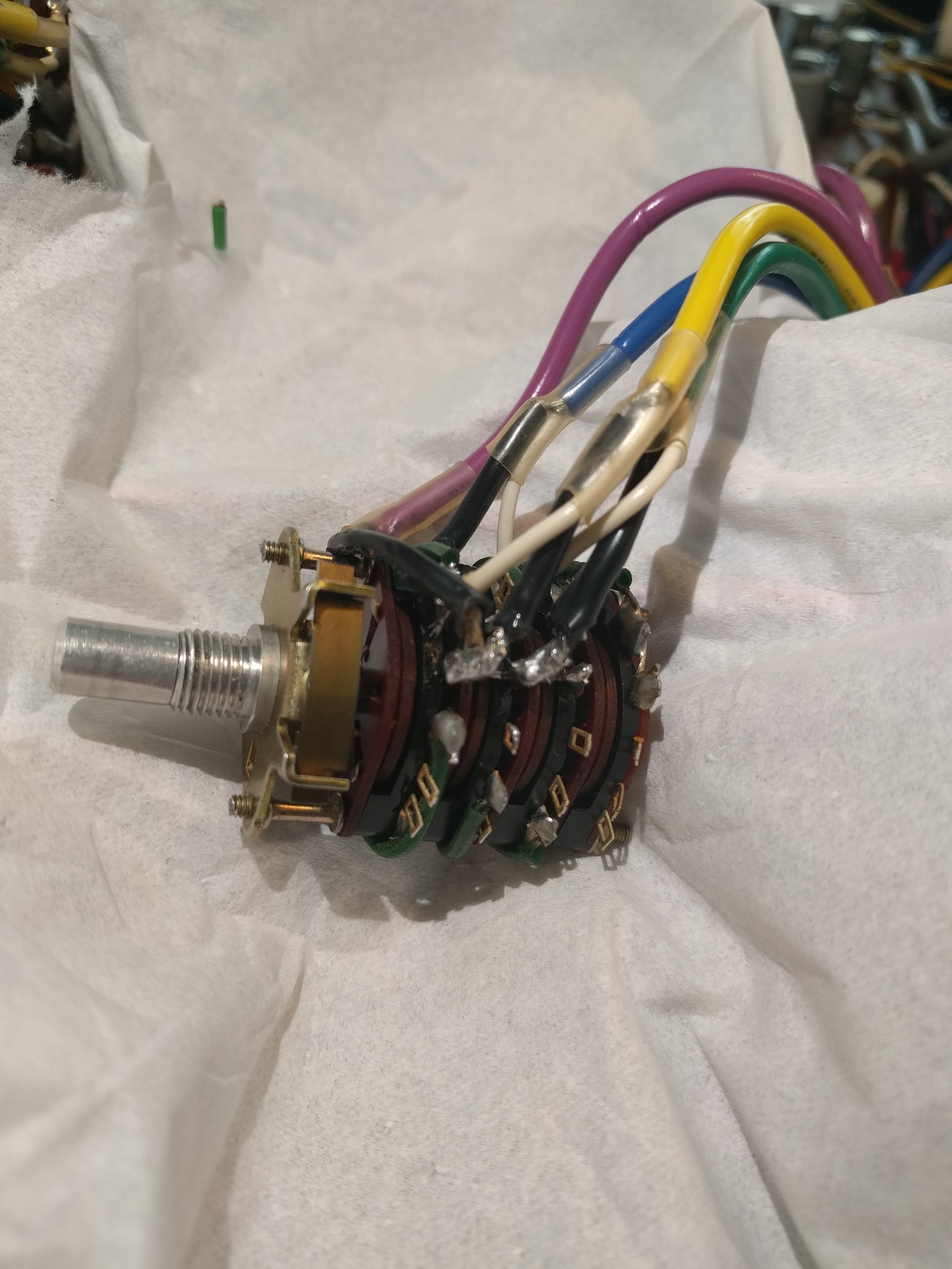
Fully cleaned and soldered
Before soldering the light green and red/white cable, first re-mount the switch to the case.
Closing the case
First don’t forget to remount component (1) and re-plug connector (2).
Finally connect the cables to the echo tank again and put the case togehter again.
Ready for a test run. Good luck!
Useful links
- Space Echo replacements parts
- How to open a Space Echo (Video)
- General maintenance guide
- Roland RE-201 technical specification
Conclusion and next steps
After testing i can state: Not only is the switch working again, also mode 1 and 6 are working on the same level as the other ones. Mission accomplished.
But still, the job ain’t done. I still got the impression, level might be too low over all. Might come from an old/wrong tape (a BASF tape is used and from what i read, that might not be the best choice). Also heads will get a cleaning and de-magnetized.
Also i can hear a bit too much wow and flutter. Again as i read this might be caused by the wrong tape. I will get a service kit from www.echofix.com to replace the tape, felts and rollers.
To be continued….
Thanks for this post / tutorial it helped me greatly. I was able to successfully fix the mode selector on my Space Echo. Like you my space echo is in perfect cosmetic condition and works well but the mode selector got stuck and required a lot of force to move it just a little. I was hesitant to begin repairing without some knowledge and your post is perfect. I assumed it was a damaged brush in the multi switch jamming it. However I got half way through dismantling the switch and couldn’t see the problem. It turned out to be a mechanical problem the shaft was jammed up. Heavy duty cleaner spray did the job and some force.
Nice to hear my post was useful for you and happy you got your space echo working again smoothly. This is such a great piece of gear and it’s really cool that, with a bit of fine motoric skills, it can be maintained to work over decades (unlike today’s pure electronical gear).